
Automation Division
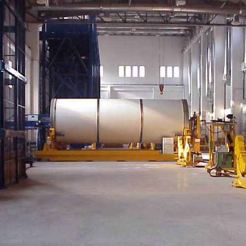
The now decades-long activity of the Automation division of the Fantini Group has led it to acquire skills and experience in various fields of industrial processes and products, from the classic sectors of moving and handling products to more specific and demanding fields such as the aerospace industry.
Specifically, the areas of use of Fantini products are:
- Aircraft manufacturers
- Aerospace
- Food industry
- Manufacture of rubber products
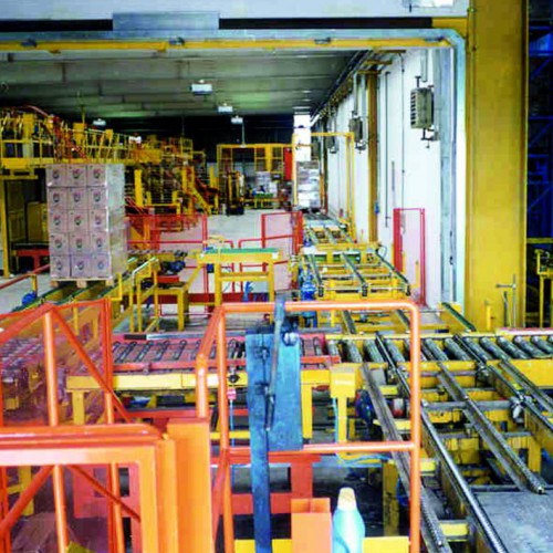
- Lines for transporting and handling materials
- Lines for packaging and palletising
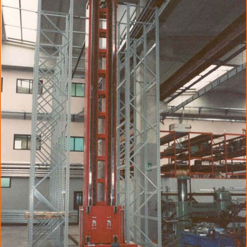
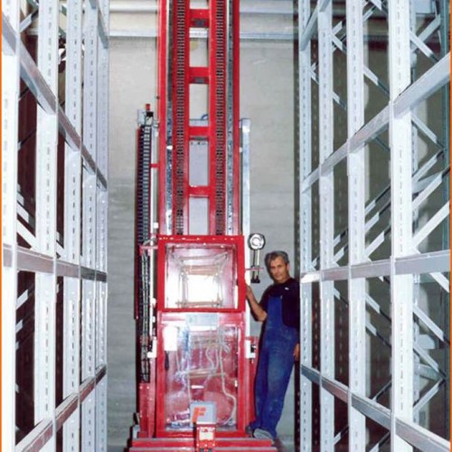
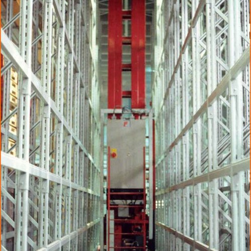
- Automatic warehouses
- AGV and transport shuttles/carts
- Lifting equipment
The Automation Division of the Fantini Group manufactures plant and technical equipment with the “turnkey” formula, designed from time to time to meet the different needs of production and lay-out of the Customer.
Below, the phases that articulate our projects:
- Inspections at the customer’s premises to understand their needs
- Study of preliminary solutions
- Preparation of estimates
- Mechanical Design
- Calculations and structural inspections
- Design of electrical plants and software
- Accompanying technical documentation for the product in compliance with applicable European Directives
- Implementation of supervision systems
- Mechanical and electrical construction and pre-assembly at our factory
- Internal testing
- Installation and final testing at the Customer
- After-sales service
- Supply of spare parts
Case History: Projects in AEROSPACE
-
Plant for handling and storage of equipment
For Fiat Avio in Colleferro the company designed and built a plant for handling thermal protections “off site” using appropriate equipment, stamps and pallets for support. The system is designed to connect the various locations where operations and work on the articles are carried out; in particular:
Environment C: all the processes of cold stratification of rubber into the stamps and segments take place in this location.
Environment for the application of adhesives, cleaning and storage: these rooms are located between the two main rooms C and D; articles arrive in the environments for application of adhesives after vulcanisation and from there, after application of the adhesive, are sent on towards the clean room.
The equipment and the stamps are sent to the cleaning station before being sent to the clean room.
The equipment and stamps are stored in the storeroom (environment E).
Environment D: the autoclave vulcanisation of the rubber, the separation of the article from the stamp and the equipment for vulcanisation by segments take place in this environment after finishing the autoclave cycle.Some of the carriers are configured on two sliding planes, the first at about 500 mm from the floor and the second at about 1250 mm from the floor; as it crosses the different environments the floor goes from the 0m level to the 6m level to return to the 0m level, so that the absolute dimensions of the runways will be 0.5 m, 1.25 m, 6.5 m and 7.25 m.
Appropriate elevators / descenders make it possible to effect the change of height. -
Splicing press thermal protection strips
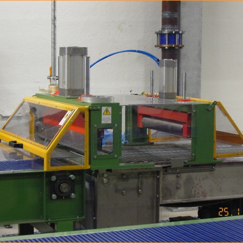
For Fiat Avio in Colleferro The company realised a press for splicing strips of EPDM rubber to feed the winding machine for the thermal protections of the segments of the P80 engine. The joint is made by heating and compression under controlled temperature and pressure.
The machine consists of the following elements:
The rotating guide band at input and output: this is two rotating discs placed respectively at the input and the output of the press; each disc has four rollers with guide bands, one roller for each format.
Press assembly: The assembly consists of two fixed plates, one upper plate and one base plate joined by four guide columns, all positioned on a support pallet. Inside the two fixed plates, the movable upper platen and the two side platens to support the containment flap assembly slide on the guide columns. The pressure in the phase of joining the strip is applied by a motorised screw jack. Between the screw head of the jack and the movable platen there is interposed a load cell for detecting and controlling the force applied to the strip. On the upper side of the movable platen is positioned the motor for the translation of the two assemblies for trimming the strips, positioned below the platen itself.
On the movable plate and the base plate are fixed, with interposition of insulation thicknesses, the two heating blocks; the aforesaid blocks are heated by means of electrical heating elements.
The two matrices, of adequate width for the strip being processed are fixed on the heating blocks; the matrices are equipped with probes for the detection and control of temperature.
Below the movable platen are positioned four adjustable spacers to limit the stroke of the movable platen, which butt up against similar spacers fixed on the base plate.Assembly of containers for strips: on the two lower mobile supports, moved vertically by the same number of pneumatic actuators, are installed two assemblies to contain the strips in the overlapping phase; each group is constituted by a linear pneumatic module completed with a containment blade.
Assembly for trimming strips: positioned laterally to the upper matrix, it is fixed on the movable plate and is formed by two slides with longitudinal translation by a screw. In the lower area of the two slides there are installed two modules with pneumatic linear traverse. Below the two modules there will be installed the two supports complete with cutting knives and positioning devices.
-
Equipment for assembly of nozzle and igniter on Zefiro 23 and Zefiro 9 engines
Purpose: assembly of nozzle and igniter for ZEFIRO 9 and ZEFIRO 23 engine
Characteristics for nozzle / igniter:
nozzle for Z9: diameter: 1256.4 mm; length: 1640.48 mm; mass: 225.9 Kg
nozzle for Z23: diameter: 1510.2 mm; length: 2023 mm; mass: 576.5 kg
igniter for Z9: diameter: 260.75 mm; length: 601.75 mm
igniter for Z23: diameter: 362.4mm; length: 727mmDescription:
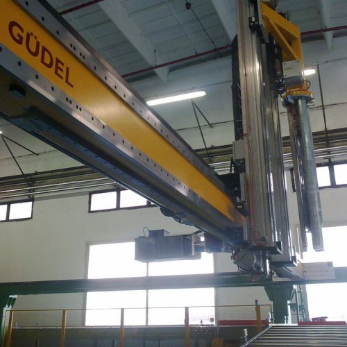
The system, realised for Avio SpA of Colleferro, is made up of a metal structure designed to move the components named nozzle and igniter for their assembly on the ZEFIRO 9 and ZEFIRO 23 engines.The structure is equipped with movement along the axis of the engine and vertical movement to allow the centering of the components relative to the engine; there is also a rotational movement to allow the turning of the nozzle from the receiving position by the bridge crane to the position for mounting on the engine. All movements are manual and controlled by special controls.
Since the engine is made of carbon fiber, it is critical to control the thrust force during the introduction of the components on the engine; for this purpose appropriate load cells have been installed, equipped with a display through which the operator keeps the force value under control and stops the insertion movement when it reaches the maximum allowed value.
At the end of the insertion of a component, the whole structure is lifted by means of a bridge crane and moved to the other side of the engine for the insertion of the other component. Furthermore, since the Z9 and Z23 engines are of different sizes, the structure is mounted on ground rails that allow the machine to be positioned according to the type of engine.
-
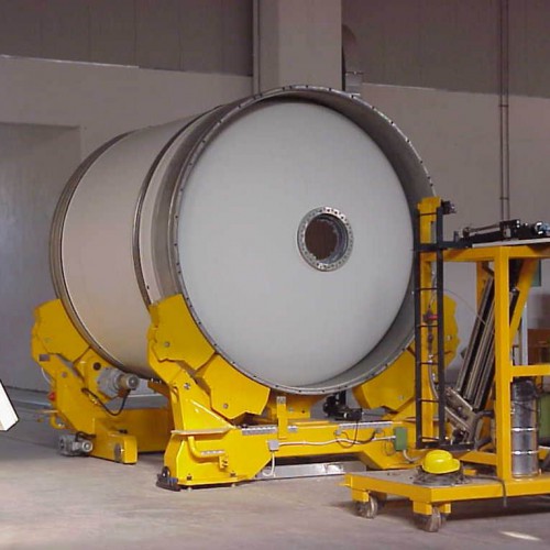
Equipment for handling segments of the Ariane 5 spacecraft
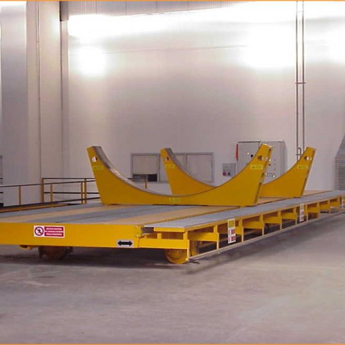
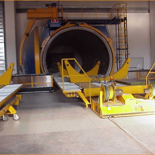
TROLLEYS TO SERVE AUTOCLAVE
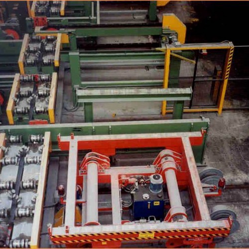
This is equipment intended for the support of the segments during the vulcanisation treatment in the autoclave; for this reason these systems are without their own motors and on board only have elements capable of withstanding the operating conditions of the cycle (T = 190° C, nitrogen atmosphere at P = 1.1 MPa). The trolley is not self-propelled, so it must be introduced and removed from the autoclave by other means of transport.LONGITUDINAL TRANSPORTER
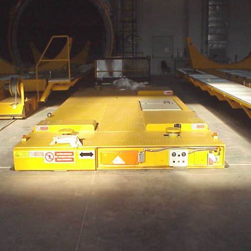
The function of these transporters is to push or pull the trolleys described above inside the autoclave or out again at the end of the vulcanisation process. During the translation of the two equipments they are attached mechanically by the manual insertion of a fastening pin; a sensor detects the presence or not of the pin and consequently allows the translational movement of the two elements.TRANSVERSE TRANSPORTER
The main function of this transporter is to move the carriage with or without a segment on board from the loading station to the runways that lead to the autoclave, and from these to the discharge station for the segment after its vulcanisation. This equipment consists essentially of a support frame in steel equipped with motorised wheels for the transverse translation and a lifting system to release the carriage from the rails.TROLLEY FOR MOVING SEGMENTS FROM ENVIRONMENT D-TOP TO D-BOTTOM
The trolley consists of a frame made of steel, above which on suitable sliding guides there move two saddles properly shaped for housing the segments.
Each saddle is equipped with its own motor to move it according to the length of the segment. The control of the movement of the saddles is effected from a panel placed in proximity to the transporter.LIFTING GEAR
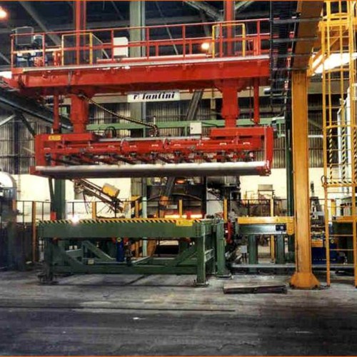
This is an automatic system for lifting the segments of ARIANE 5. The lifting gear is lifted and moved by means of a bridge crane and brought in correspondence with the lifting position where, after a series of automatic operations of centering and rotation, it engages the segment.
Projects in the CHEMICAL INDUSTRY
-
Building and installation of a fork lift truck
For Procter & Gamble, Pomezia, the company designed and manufactured a fork lift truck with gripper chains suitable for handling drums of detergent. The fork lift truck is made of structural carbon steel and stainless steel guards.
The truck receives single boxes or bundles from the existing line and transports them from a level +1000 mm to level +4685 mm.
The opening of the gripper chains is adjustable via a geared motor and a digital counter for displaying the position reached.The gripper chains are installed on a movable element driven by means of recirculating ball guides, all controlled by a screw jack driven by a geared motor in order to allow adjustment of the height of the chains to allow the drums to be picked up correctly, keeping both the carrying plane of the lower feed belt and the upper unloading one fixed.
Productivity 120 drums / min. -
Hopper lift line 1 - Goldie
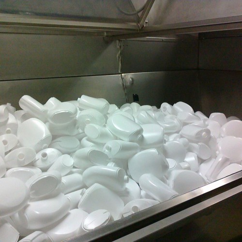
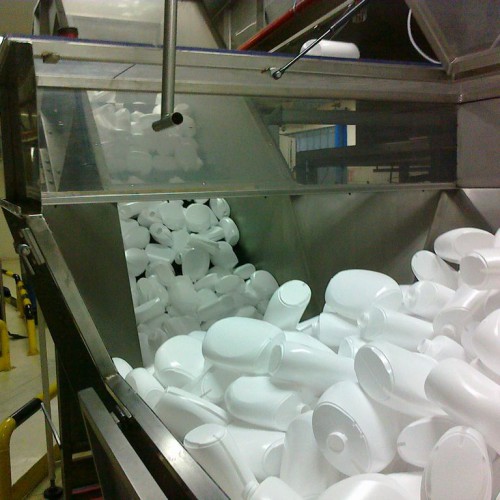
For Procter & Gamble Pomezia, the company designed and built a plant for feeding empty bottles into the Pace orienting machine. The supply is composed of 2 lift hoppers for Line#1G and Line#3G.
Specifically, a hopper lift is composed of a hopper with decking that allows the operator to turn containers of bottles inside it; a conveyor belt placed on the bottom of the hopper sends the bottles to the inclined belt which in turn uses an output chute to feed the downstream machine.
The capacity of the hopper is sufficient to contain 1000 bottles of format 2.5 litres. -
Automated Warehouse
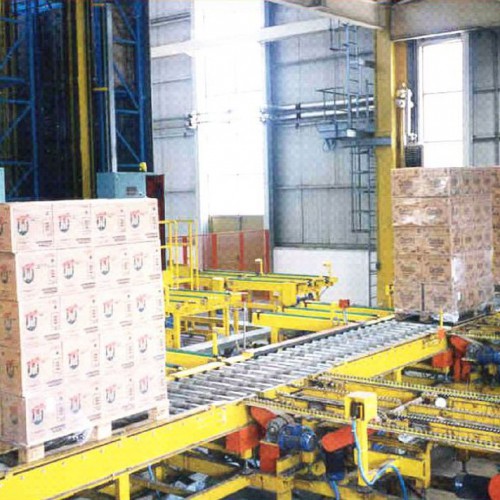
At the Lever factory in Pozzilli (IS) the company designed the new automated warehouse adding an additional lane managed by a new stacker crane. The product to be moved is a pallet stacked with boxes or bottles of detergent.
The characteristics of the product to be handled are the following:
- Pallet dimensions: 1200x800x2050 mm
- Maximum pallet weight: 1000 kg
The supply consists of:
- 6 chain conveyors as bays for loading and unloading pallets
- 1 pair of metal shelves
Projects in the FOOD INDUSTRY
-
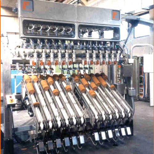
Machine for handling wafers
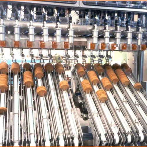
The plant in question was designed and built for the Italian and French companies SAGIT and MIKÒ, to handle the transfer of wafers to the feed belt of the oven. The plant is composed of:
- 12 conveyor belts with independent drives (l = 1200 mm, w = 150 mm, inclination: 30°)
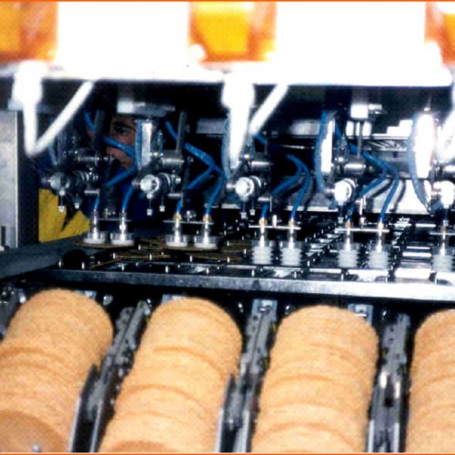
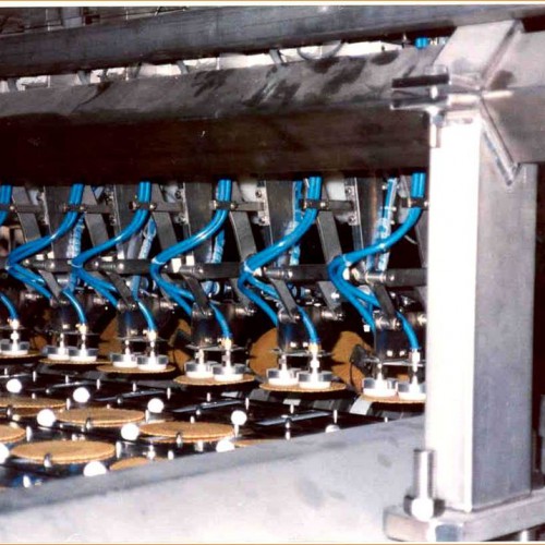
- 12 manipulators fitted with pick & place trolleys with independent drives
- 1 belt recovering waste (l = 3400 mm, w = 350 mm)
- Electrical panel and control desk.
In the construction of the various elements we have used criteria of hygiene and cleanliness typical of the food industry; in particular the design and realisation have been performed so as to exclude the presence of welds and flat surfaces on which dirt can settle.
WORKING CYCLE
The wafers are loaded manually in stacks on the conveyor belts in carriers; during this phase, the wafers pass between calibrating frames that define the maximum diameter.
The waffles advance along the belts until they reach the presence photocell (optical fiber) which corresponds to the gripping position of the manipulators.
Once the wafers are in the gripping position, the gripping arms of the manipulators rotate downwards by means of a cam, while the carriage moves toward the feed belt.
When the carriage arrives at the gripping point, the suction cup is brought in contact with the surface of the wafer and picks it up; then the carriage starts the translation with the wafer in a vertical position and, after clearing the bulk of the belt, the arm is rotated by the cam system.
When the carriage arrives at the deposit position, the wafer is positioned inside the reference marks placed on the feed belt of the NIC oven and released there. -
Line for production of cones
The plant in question has been designed and built to handle pallets and trays to serve the cone production line for the Italian and French companies SAGIT and MIKÒ.
In the construction of the various elements of a plant the criteria of hygiene and cleanliness typical of the food industry have been used; the structures of the conveyors, elevators and index axles are made of AISI 304stainless steel, the structure of the manipulators is made of painted carbon steel, while the mobile unit of the manipulator and the gripper are made of aluminium.
The stack formed by the full trays, coming from the Bakery, is deposited on the first conveyor of the loading area and advances up to engage the last accumulation station; from there the trays are picked up individually by the destacker manipulator, translated and deposited on the first of a chain of conveyors forming the conveyor line for full trays of height 2560 mm; at the end of destacking, the empty pallets are sent to the area for transport of empty pallets.
From the conveying line the filled trays are transferred, one at a time, by means of an orthogonal transfer member and a chain conveyor, to the production area and on to the area for coupled discharge (wrapping + biscuit); here the tray is taken over and centered by aligning the rows of trays with the channels of the discharge lanes of the lines for filling cones, after which discharge is effected by means of a system of pushers under pneumatic control.
Once unloading is completed, the empty trays are sent to an elevator, passing on chain conveyors and on an orthogonal transfer member; the elevator lifts the trays to a height of 5285 mm, where they are unloaded on a series of chain conveyors for accumulation through which they arrive at a descender which brings them back down to a height of 2560 mm, unloading them on the loading unit of a stacking manipulator which picks up the tray at a height of 2,560 mm and deposits it at a height of 560 mm on a waiting service pallet.
At the end of stacking, the stack of empty trays is transferred to a chain conveyor and from there to the discharge conveyor from which it is picked up using a fork lift truck.
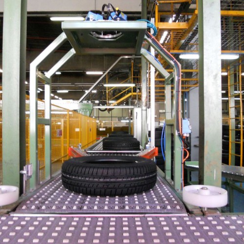
Projects in the TYRE INDUSTRY
Automatic warehouse for tyre carcasses
Line for palletising tread strips
Finishing line for tread rings
Automatic production of tread rings
Cooling lines serving extruder
Wrapping Machine for tread rings
Palletising system for tread strips
Unloading line for Saspol press
Terminal line calender rubber for tyres
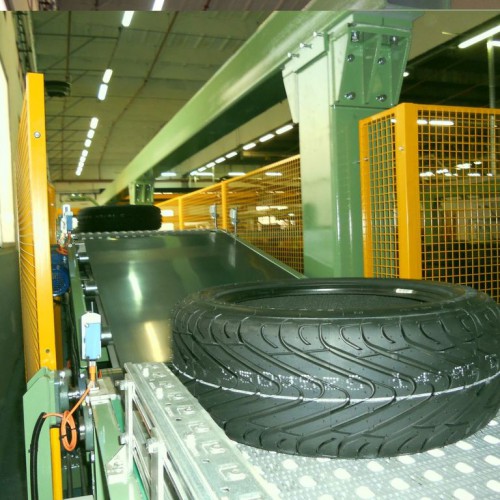
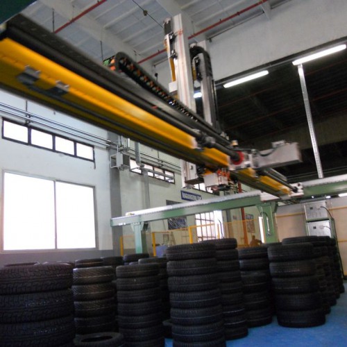
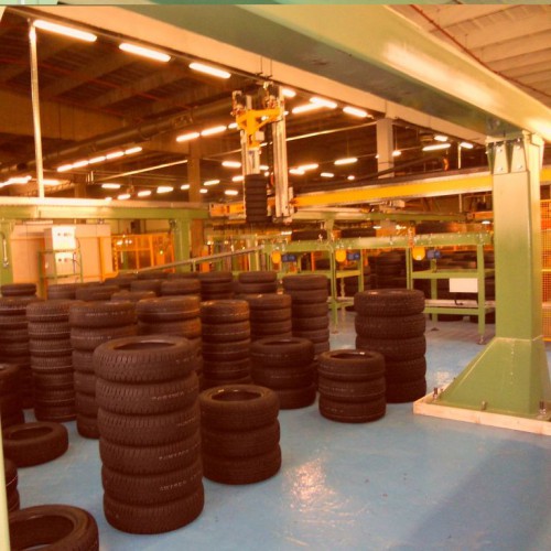
Manipulator for palletisation of vulcanised tyres
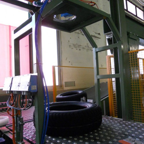
Manipulator for loading and unloading carcasses to and from the conveyor chain
-
Automatic warehouse for tyre carcasses
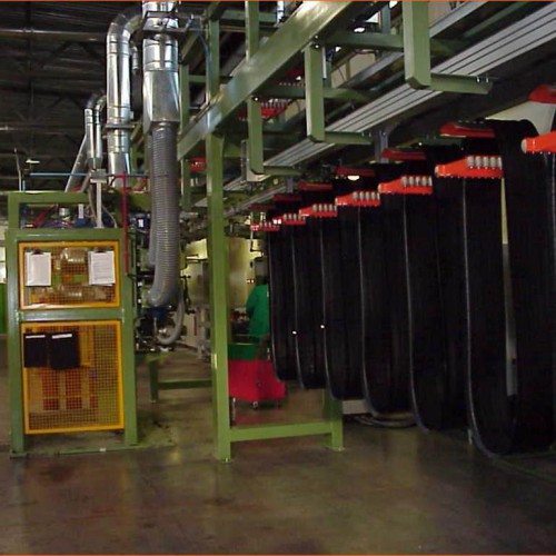
At the plant of Trelleborg Wheels Systems the company built an automatic warehouse for the intermediate storage of carcasses from the manufacturers which are sent on, after appropriate ageing, to the BOM vulcaniser.
The carcass is deposited by the operator in the input station and transferred automatically to the drawing unit of a manipulator that lifts it and puts it on an empty tray.The tray with the carcass is then sent to the automatic warehouse for storage; the tray is then transported to the central corridor, where the stacker crane picks it up and deposits it in one of the 144 locations of the warehouse by means of a shuttle.
After proper ageing and selection by the operator, the carcass (in the tray) is transferred to the output station for the next stage. Here the operator picks it up and the empty tray is cleaned by a special brush and automatically recirculated.
-
Line for palletising tread strips
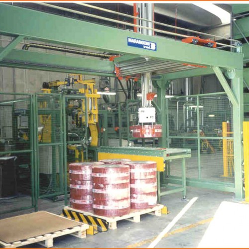
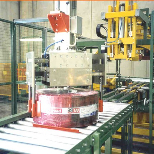
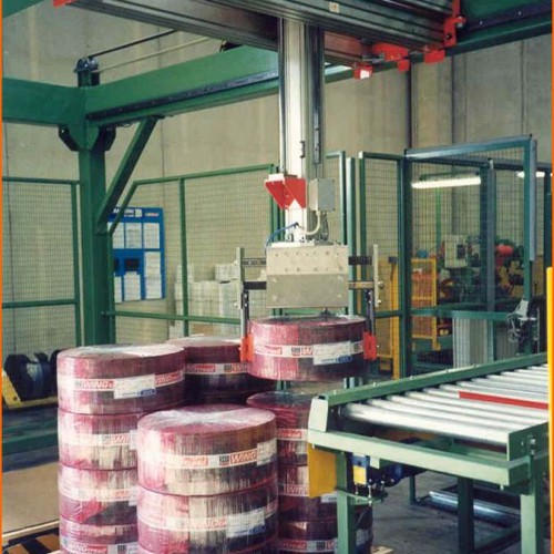
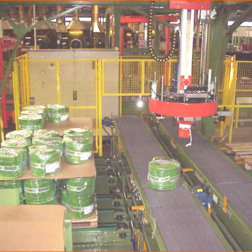
For the Marangoni Group the company designed and built a plant to palletise rolls of tread for the tyre retreading market.
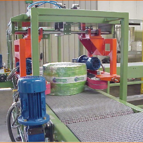
It is composed of a series of belts and rollers serving a wrapping machine and a palletiser. The rolled up tread band is discharged on the conveyor output of the winder (height 450 mm) and from here transferred onto the rising accumulation belt that takes it to 1000 mm.
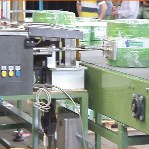
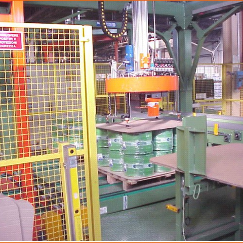
When the roll arrives on the roller conveyor a with 90 ° bend, the operator applies an identification label, and then the band moves inside the wrapping machine where it is centered and wrapped with 2,4 or 6 layers of film. At the end of wrapping, the roll is transferred onto the roller conveyor inside the palletiser and as soon as it bumps into a suitable abutment a sensor triggers the descent of the manipulator which picks up the band, moves it and finally deposits it on the pallet.
This work cycle is repeated until the completion of two pallets, that can be differentiated by the number of rolls per layer and the number of layers.
To allow the operations of loading and unloading of pallets in conditions of total safety, the front of the palletiser is protected with a light curtain that stops any hazardous motion in case of interception of its light beams.
-
Finishing line for tread rings
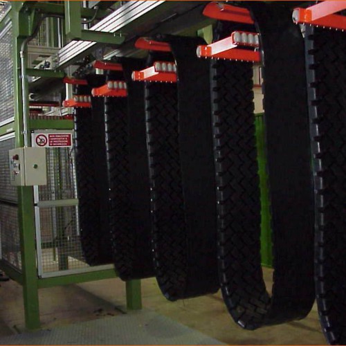
For the Marangoni Group (Marangoni Tread and Marangoni North America) the company has made finishing lines for rings stamped in the Alpha Ring plants; in these lines the rings are brushed, dipped and wrapped for palletising.
Each line is made up of the following elements and locations:- station for manual loading of rings on baskets
- conveyors serving machines for rasping and dipping, with a total length of about 40 m
- 2 rasping machines
- 1 dipping machine
- inspection station
- 1 winder
- 1 elevator / descender serving a recirculation line for empty baskets
- upper line for recirculation of empty baskets
- 1 descender / elevator serving lower line
- 2 ladders and catwalk for maintenance of the upper line for recirculation of baskets
-
Automatic production of tread rings
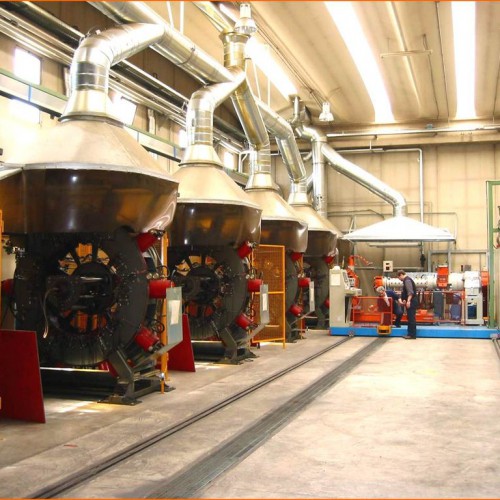
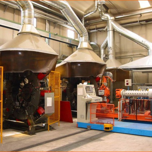
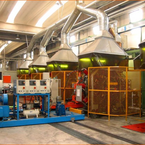
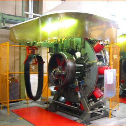
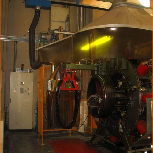
The plant in question, implemented for various establishments of Marangoni (Marangoni Tread, Marangoni North America, Ellerbrock) is used for production of vulcanised rubber rings from the raw extrudate. The plant consists of:
- Trolley to carry extruder
- 6 centripetal machines of STANDARD or SPECIAL type wtih rotating core complete with a manipulator for automatic discharge
- 1 line serving centripetal device
- 1 self-propelled line serving the trimmer
- 2 self-dimensioning trimmers.
The trolley carrying the extruder, moving on rails on the ground and starting from the first press, serves in a sequential manner the centripetal affixing on the core in rotation the amount of extrudate established for the size of the ring in question. At the end of this deposit the core re-enters, the stamps close radially towards the core and this begins the vulcanisation cycle which finishes with the automatic discharge of the ring on the manipulator on the left side of the machine and with the calling of the trolley serving the centripetal device.
The latter, coupling with the machine that made the call, is arranged with the output saddle in the low position, and gives permission for the discharge; once it has received the ring, it is blocked, raised and moved to the transfer station on the self-propelled trolley that serves the trimmer.
At a signal that the trolley is ready, the descender is released and sent down to the height of the discharge, and the ring is then transferred to the self-propelled unit by a pneumatic pusher. At this point the carriage moves until it comes in correspondence with the trimmer set for that format of ring and deposited on it; then the trimmer rotates into its working position and the deburring cycle starts at the end of which the operator manually sees to the removal of burrs sideways and the removel of the ring.
-
Cooling lines serving extruder
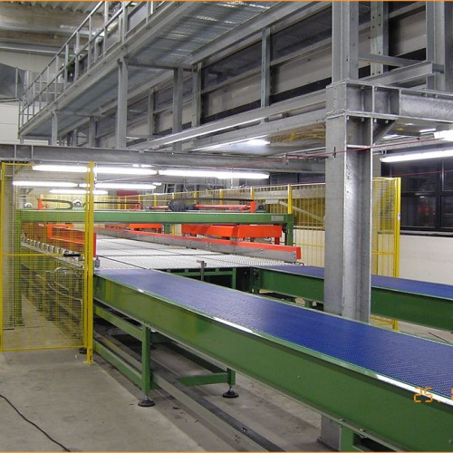
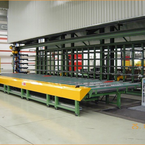
For the Marangoni Group (Marangoni do Brasil and Marangoni Tread North America) the company has made two lines for cooling rubber as output from an extruder. The supply is made up of a conveyor to feed an extruder and a series of roller conveyors which convey the rubber strip to the cooling tanks.
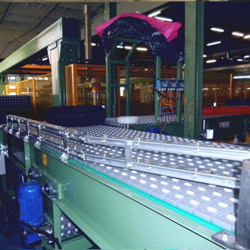
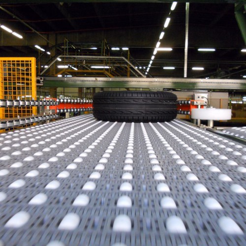
The latter are arranged on four or five levels (depending on the layout) and are equipped with Intralox belts which carry the strip. At the exit from the cooling tanks the rubber passes on a conveyor belt with a cutter for cutting the strip to size.
The bands thus obtained then come to a transporter that takes them to a weighing station; the bands are then sent to the return line where they are wrapped and evacuated on the unloading roller from which the operator picks them up with a partner.
To allow easy performance of operations of initial insertion of the strip and maintenance, there is a walkway along the entire length of the tanks, with access at both ends.
-
Wrapping Machine for tread rings
The machine, supplied to the Marangoni Group, was designed and built to carry out the automatic wrapping of tread rings coming from a line of rasping and dipping.
The machine receives the ring to be wrapped by the action of an ejector present on the recirculation line for baskets corresponding to the wrapping machine. The ejector pushes the rubber ring on to the forks of the wrapping machine and once this has received the product, they are put in rotation which allows the subsequent formation of the wrapping.
During the winding step a layer of polythene, dispensed by a motorised unwinder, is interposed between the layers of the ring to prevent the contact surfaces from sticking to each other. At the end of the winding the polythene is cut by a hot wire device. The cylindrical conformation of the wrapping is guaranteed by the action of two semicircular containment rollers that are in contact with the wrapping as it is wound on. After the winding, the ring is rotated further to allow the application of adhesive tape on its circumference; the adhesive tape is dispensed by a specific tape dispenser assembly and cut automatically by means of a knife.
The bundle thus obtained is made to fall by gravity into a special saddle by means of a retracting movement of the forks. At this point the saddle, that to accommodate the wrapping was taken to a position just beneath the forks, is lowered and moves horizontally bringing in correspondence with a roller conveyor to which it is rigidly coupled by the insertion of a pin in a special saddle. Then, with a tilting movement of the saddle and the roller conveyor the ring is deposited on the latter. After tipping the roller serves to transfer the ring on a conveyor chute that is inclined downwards.
The machine is completely protected with wire mesh grilles that separate off the dangerous moving parts; also to facilitate the operations of maintenance and adjustment in height there is a ladder that allows operators to easily reach the various elements.
-
Palletising system for tread strips
This set of machines, made for the Marangoni Group, performs the function of a palletising system and it is positioned downstream of the two lines of rasping, dipping, winding and wrapping.
The rolls of rubber from the two upstream lines, wound and wrapped with transparent film, transit on Intralox belts until they reach a station where they are repositioned according to the position they will assume in the pallet. Continuing the path the bands first come to a labelling machine where labels are affixed, and subsequently to the drawing unit of the bands manipulator. The latter picks up the rolls from each of the two lines alternately and deposits them on the corresponding pallet.
At the end of a layer, the manipulator picks up a special interlayer from stock and deposits it over the bands, and then continues to fill the pallet. When both pallets are complete, they are moved on to a shuttle with two holders that slides on rails on the ground for transfer. At the same time two empty pallets, passing on appropriate conveyors with three chains, reach the stations for filling pallets and a second manipulator picks up empty pallets (one at a time) from the empty pallet stores and places them on the transporter to feed the pallet-filling stations.
The shuttle takes the pallets on a transport line that serves a wrapper and, after wrapping, the pallets continue on the transport downstream, from which they are removed by an operator with a forklift.
-
Unloading line for Saspol press
For the Marangoni Group the company has realised three lines for unloading from Saspol presses. At the end of the vulcanisation cycle of the press the bands are picked up by a manipulator (forming an integral part of the press itself) and unloaded on to the belts of the discharge line. The line is made up of:
- collection belts for flat bands press 10.5 m: these are twenty-one Intralox belts with length of about 2500 mm and width of 250 mm with liftable panels interposed at the ends to regulate the entry of the bands to the line for cutting burrs and winding
- machine for cutting longitudinal burrs
- speed-limitation device, necessary to allow the winding of the band at a constant speed
- drum
- roller conveyors for unloading
-
Terminal line calender rubber for tyres
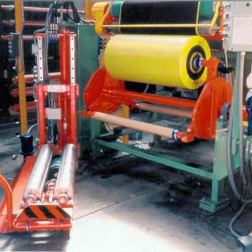
For the Marangoni Group the company has designed and made some lines downstream of the calendering machine intended for the treatment, wrapping, taping and unloading of the leaf rubber output from the calendering machine.
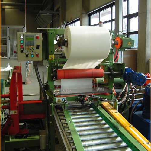
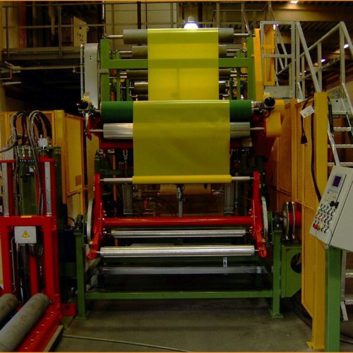
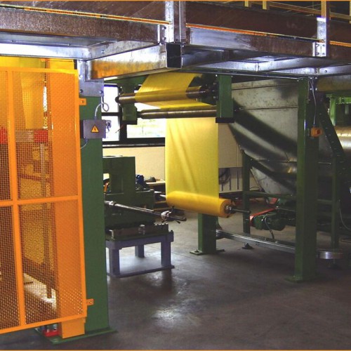
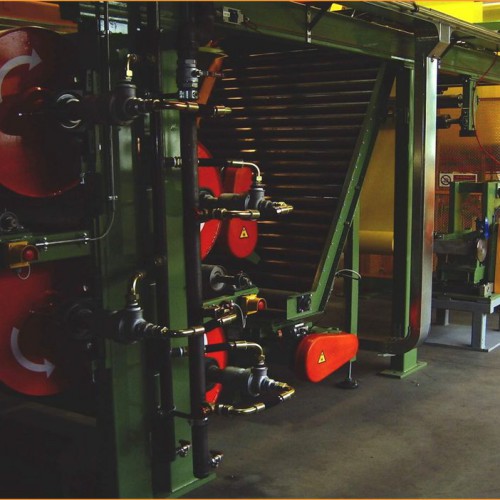
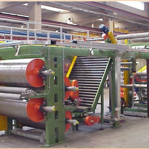
On leaving the calendering machine, the web passes through four cooling drums; these drums, diameter approximately 700 mm, are made of steel and are equipped with rotary joints for connection with the cooling water plant. After passing the rollers, the fabric comes to an inclined roller conveyor where is sprinkled with powdered rubber; the feeding of the powder is ensured by a system of hoppers and conveying screws.
After being sprinkled with powder, the canvas passes through abrushing station that has the purpose of evenly distributing the product and removing excess deposits. Downstream of brushing, passing on to a horizontal roller conveyor, the canvas comes to a drum driller; before being drilled, however, the fabric passes through a series of return drums which serve to couple it with a film of polythene coming from a distribution container placed on the ground. Because the fabric must always remain taut during this processing, and since the calendering machine keeps it always in motion, to allow the stop of the reel winder at the end of the winding of a coil there is a handle with two loops (speed limiting control) .
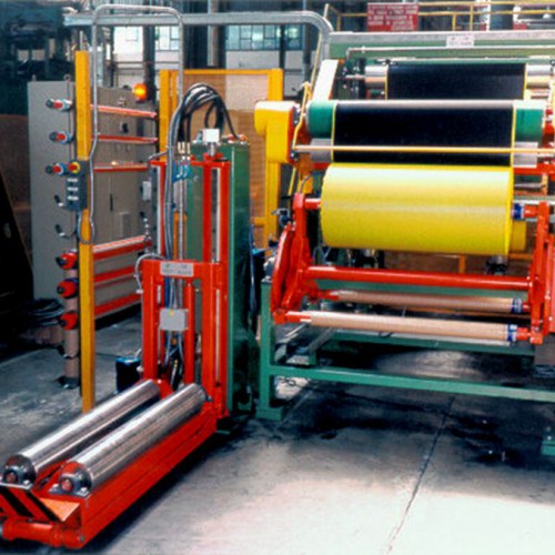
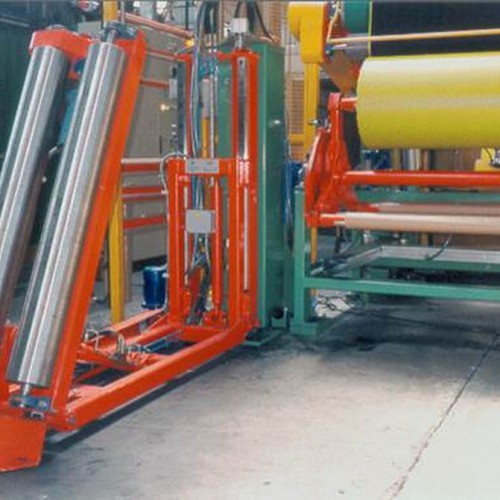
Downstream of the speed control, the rubber is wound on a cardboard core manually placed on a reel with three arms. This solution is related to the continuous production of the calender machine, which demands the winding of a second arm when the first is finished and must be unloaded. For the unloading of the coil, the operator deposits it on a wheeled device equipped with a raisable and tiltable cradle device which makes it possible to receive the roll in a horizontal position (discharge position for the reel) and to bring it to a vertical position.
Inspection and maintenance of the components placed at height is easy thanks to the construction of a footbridge with access stairs. -
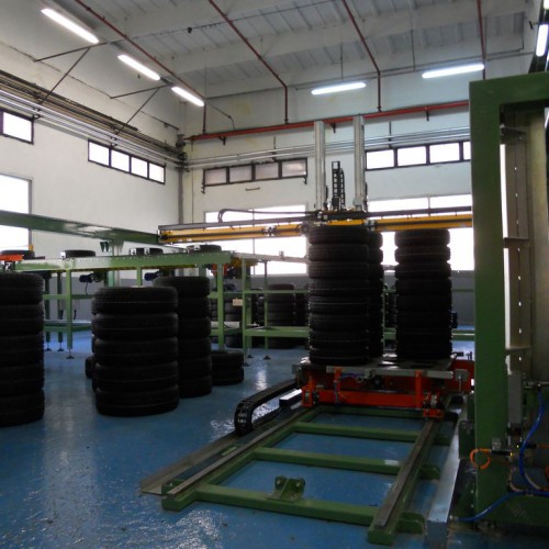
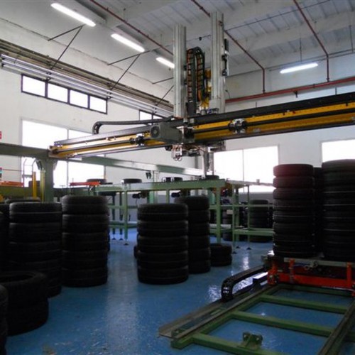
Manipulator for palletisation of vulcanised tyres
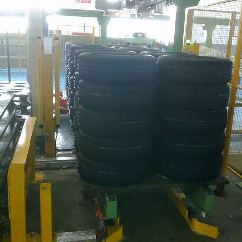
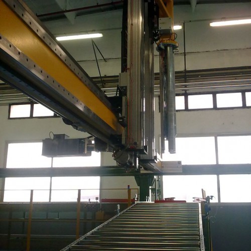
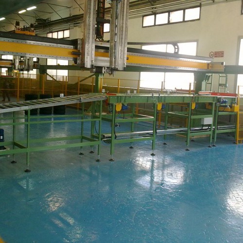
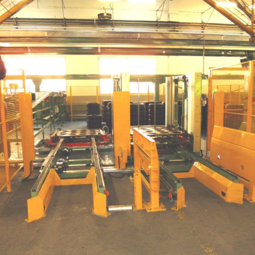
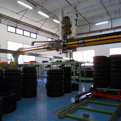
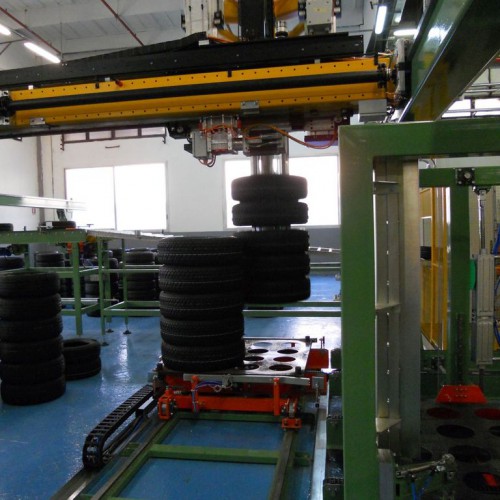
For Marangoni Tyre at Anagni the company designed and realised a palletisation system for shells composed of a Cartesian co-ordinate portal with two independent bridges. This is a dynamic warehouse able to pre-order tyres in the two buffer areas, after visual inspection of the product code. The gripper is suitable for storage / retrieval of single shells and the formation of stacks of shells to max height 1500mm.
The warehouse is divided longitudinally into two areas. It is fed by a transport system that receives in input the shells, manually loaded by an operator on to the suspension bars in the section for visual inspection and automatically unloaded from the latter by a mechanism under electropneumatic control. The transport at the head, by means of a swivelling conveyor, feeds a double longitudinal transport line which independently serves the two rows of rollers at the center line of the buffer areas of the warehouse.
The tyres, now identified by reading the barcode with barcode reader systems, arrive on the input roller and are transferred to the buffer by means of two Cartesian coordinate robots (one per section) which carry out the offsets in the two co-planar horizontal axes, while through a gripper, they perform the vertical lifting of single shells. The gripper is positioned at the centre of the tyre cavity and through the opening of the arms puts pressure on the rubber to lift it. The Cartesian robots have performance that enables them to handle up to 500 tyres / hour.
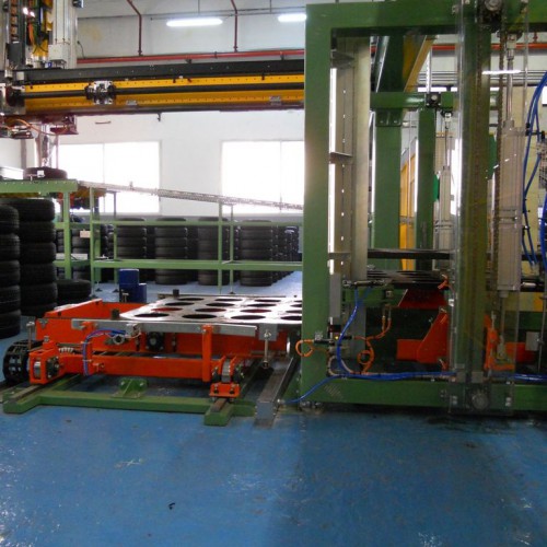
The buffer is completely mapped (438 positions on the ground in the whole warehouse, corresponding to as many possible stacks of tires) in such a way as to allow movements to be tracked. Once the preparation of a vertical stack is completed, it is picked up and transferred to the area for palletising. The robots pick up the single stack of tyres from the ground and deposit them on specific loading units, which are pallets, consisting of metal plates that can be picked up by forklift trucks. When a loading unit is finished, it can be generally be composed of four, three or two stacks of shells with the same code and measurements.
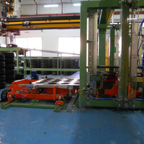
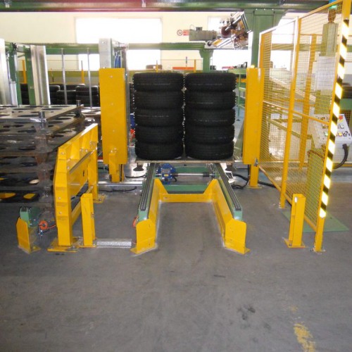
Each bridge is supplied by a separate pallets line with a destacker. The pallets are stored in piles with no more than seven levels and transferred through the transport chain to the destacker. One at a time the are sent inside the warehouse, where they are transferred through a specific shuttle to the palletising area. When the pallet is full, it will be directed to the respective output and collected by an operator with an electric pallet transporter.
-
Manipulator for loading and unloading carcasses to and from the conveyor chain
For Marangoni Tyre of Anagni, the company designed and built a system for loading carcasses on to the R8 transport chain. The system involves the removal of carcasses from trolleys or air carriers for shells coming off the production line and positioning the same on R8 swing-trays.
Loading is done by an anthropomorphic robot, with an appropriate gripper, which deposits the carcass on a pantograph mechanism provided with a movable cradle. The cradle positions the centre of the cavity of the tyre to correspond to the path of movement of the swing-trays allowing them to take it. A batch coming from the lines takes precedence over a batch from the trolley.
The type of carcass being lifted is detected by reading the barcode of the trolley, to which is associated a type of shell, or by reading the bar code placed on the shell itself for those coming from the lines. The PLC of the system communicates to the company server the records of the carcasses unloaded from trolleys (bar-code of trolley and bar-code of carcass) and those from air carriers (reading the bar-code on the bead of the carcass).
All this is completed by an automatic handling system for trolleys consisting of a supply system for full trolleys consisting of a lane with a capacity of three full trolleys and a system for motorised movement and forks coupling to the tubular base of the trolley to drag; shuttle to transfer trolleys from the full trolley lane to the station for emptying and the corresponding exit lane for empty trolleys, of construction similar to the feed lane for full trolleys.
The opening of the shelves of the trolley is performed by an automatic device. There is also a roller to collect waste of unrecognised carcasses and a transport connection from the production lines to the drawing unit made up of Intralox belts. The system is capable of handling a total of 500 carcasses / hour.
Case History: Projects in PACKAGING AND PALLETISATION LINES
-
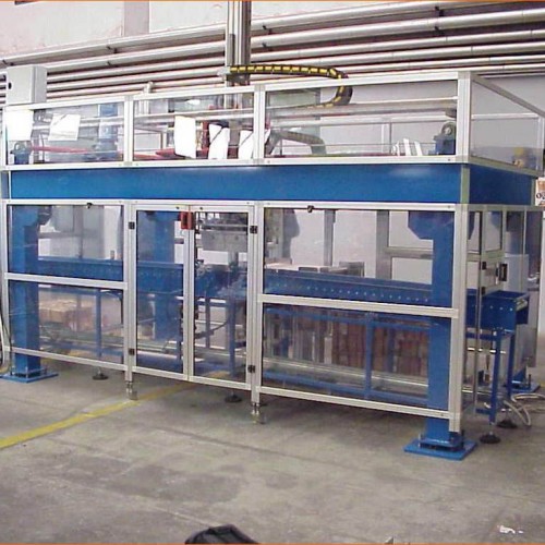
Automatic packaging lines for boxes of euro coins
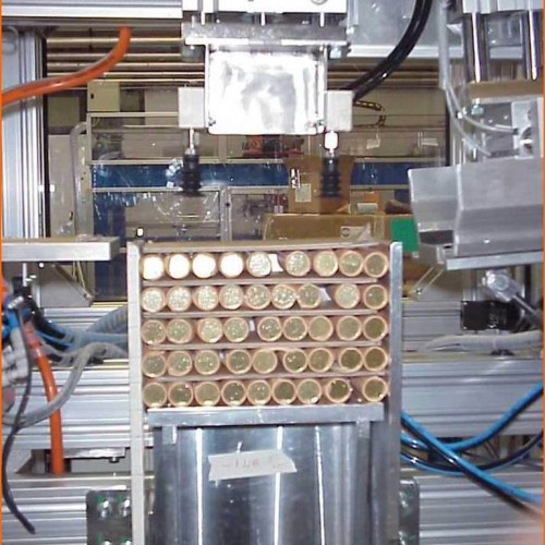
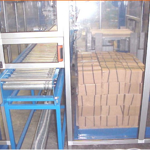
At the Government Printing Office and Mint there have been installed two automatic lines for packaging rolls of Euro coins in boxes and for the palletisation of said boxes.
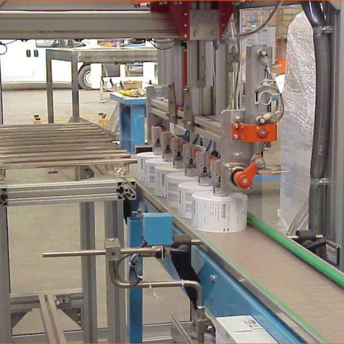
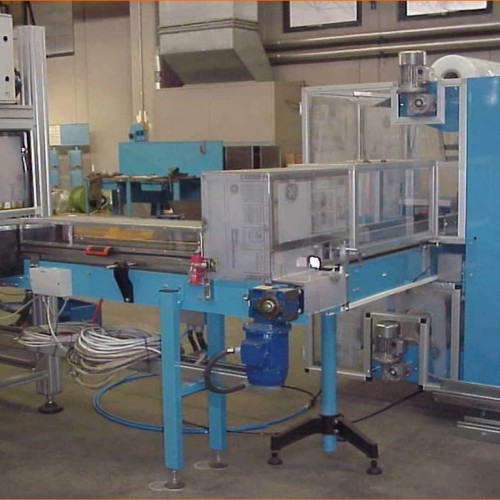
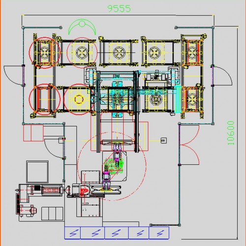
Each line consists of two portions: the packaging line and the wrapping line. The function of the system is to prepare boxes containing rolls of coins (packaging line) and to send them to the wrapping line where they are closed with adhesive tape, strapped, labelled and, finally, deposited on a pallet.The plant receives the rolls from four packaging machines placed along a belt (each machine pours the rolls into one channel of the belt) and sends them to a cartoning machine. Here as many layers of rolls are formed as are necessary for the format in production (possibly with interposition of interlayers of cardboard to obtain a better filling of the box), after which they are transferred inside a cardboard box previously formed by a cardboard forming machine.
-
Automatic plant for packaging paper rolls
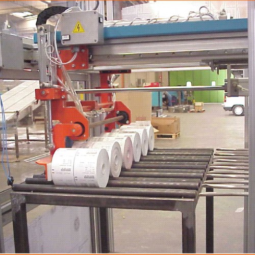
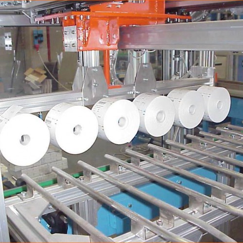
The plant, built for the Government Printing Office and Mint, is designed to carry out packaging of boxes of paper rolls used for playing the Lotto Game.
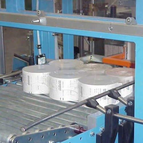
One line, upstream of the system, forms the rolls and moves them to a surface, equipped with special guides, to which the rolls will be transferred by means of a special manipulator; subsequently, another manipulator takes one row of small rolls at a time (6 rolls) and deposits it, by tilting, on an Intralox belt; which has a barcode reader that can read the bar codes of the rolls.
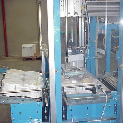
If the code matches the one that is expected then the roll continues its path, while if the code is not correct you will hear a beep and the roll in question will not be allowed to continue (the belt stops and an operator must remove the roll and restart the line). The rolls, arranged in two rows of three rolls each, reach a shrink tunnel where they are packaged with a transparent film; subsequently the parcel arrives at a cartoning machine where a manipulator with suction cups takes hold of the package and deposits it inside a box that has been formed in advance.
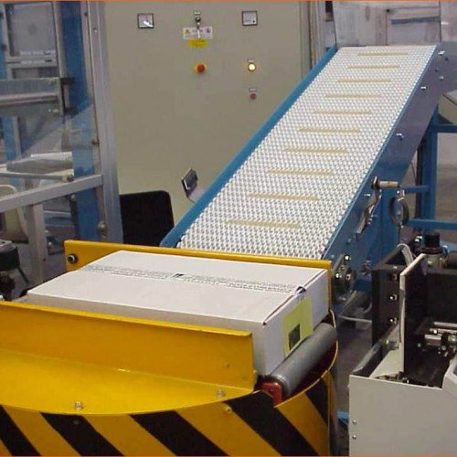
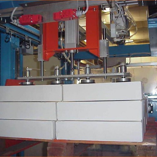
The box, closed with adhesive tape, then arrives at a rotary table where it is first labelled and then rotated 90 ° to enable the box to advance to the front of the short side. Finally, an Intralox belt conducts the box to the pickup station of a palletiser; when two boxes are present in the pickup station, a suction gripping device picks up the boxes and deposits them on the pallet; the latter is placed on appropriate supports with variable height that makes it possible to perform the deposit always at the same height.
Case History: Projects in LINES FOR TRANSPORT AND HANDLING
-
Plant for collection and accumulation of reels of tissue paper
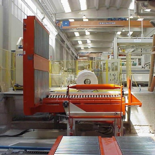
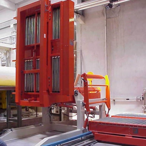
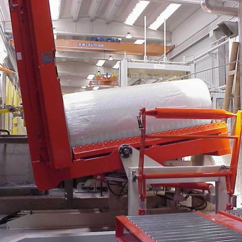
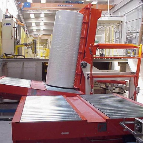
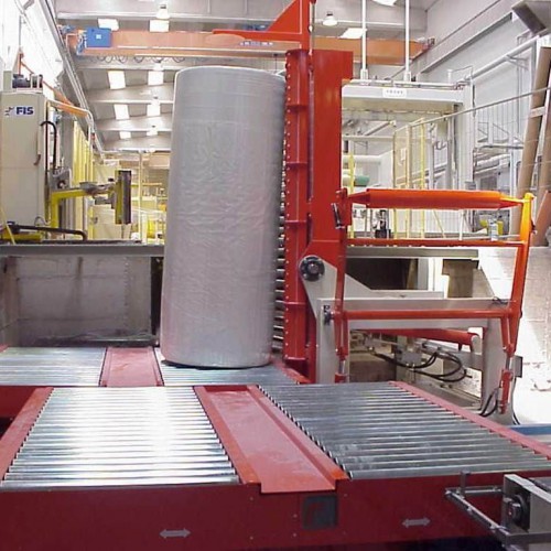
The reels come from a wrapping machine and arrive, arranged in horizontal position, on a tilting device provided with a suitable containing saddle. The latter is equipped with a pusher and lower idle rollers to allow an easy approach of the reel to the vertical tipping plane; also one of the two sides of the saddle is hinged so as to allow its opening, after tipping, to release the reel.
Downstream of the tilter there is a shuttle to effect the transfer of the reel to correspond to the belts for accumulation. The shuttle will be managed in such a way that it autocentres with the first accumulation belt according to the diameter of the reel, transmitted through a signal given by a series of photocells, thereby depositing the coil centered with respect to the belt.
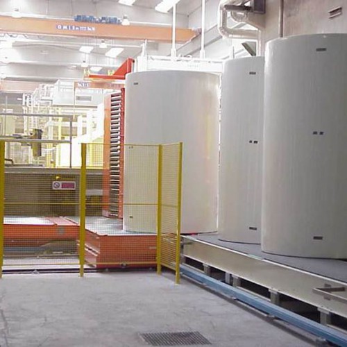
The storage line is composed of five Intralox belts, length about 6500 mm each, to accommodate two, three or four reels according to the diameter. The system of transfer from one belt to another is such that when one belt is full all the reels are transferred to the downstream belt. When the reels come to the last belt of the line they are removed with a suitable lifting device.
All transport is performed with Intralox belts in Acetal; the sliding surface is formed by two belts 800 mm wide with a central gap of 400 mm, for a total width of 2000 mm. The plant consists of the following elements (see our Drawing 04-1006-00):
- 1 tilter with saddle for containment and Intralox Acetal belt conveyor
- one shuttle with Intralox belt transport on board
- 5 Intralox transport belts each length = 6500 mm. Total width = 2000
- electrical installation and management software with Siemens S7 PLC
- guards around the tilting reel and traversing shuttle
- impact protectors for the area for unloading the reel
-
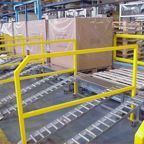
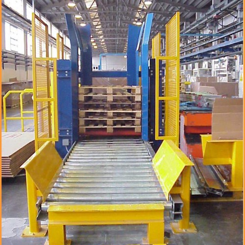
Pallet handling lines serving presses
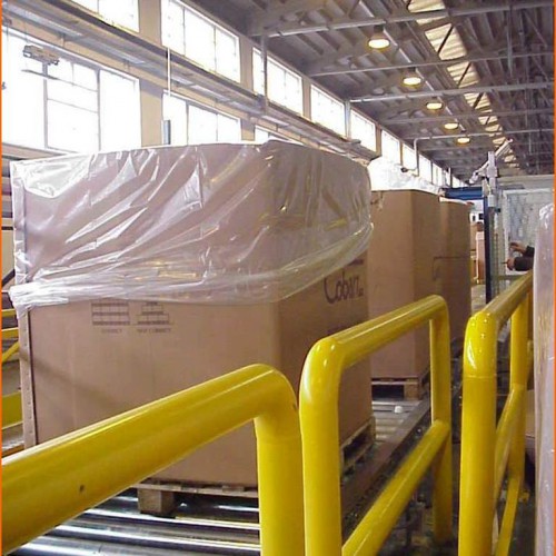
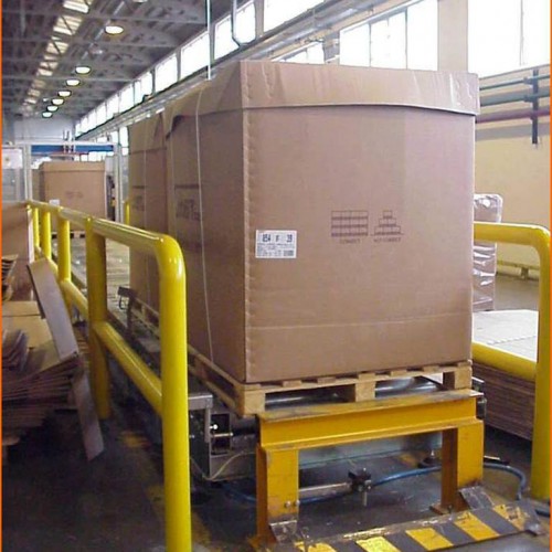
The plant, made for the establishment Cobarr SpA of Anagni, is used to move empty pallets towards the presses and take full pallets as output from the presses to a discharge line. The plant can be divided into three sectors:
- The line to supply empty pallets, consists of: roller to load empty pallets, pallet destacker, roller for accumulation with room for six pallets, descender with chain conveyor, chain conveyor to serve descender, chain conveyor to serve shuttle.
- Line for loading / unloading presses, made up of: shuttle with two mobile platforms , 21 bays for loading / unloading presses.
- Full pallet evacuation line Consisting of: 1-chain conveyor serving shuttle, 1 chain conveyor serving elevator, 1 elevator with chain conveyor, 2 accumulation rollers with six places, 1 unloading roller for full pallets.
-
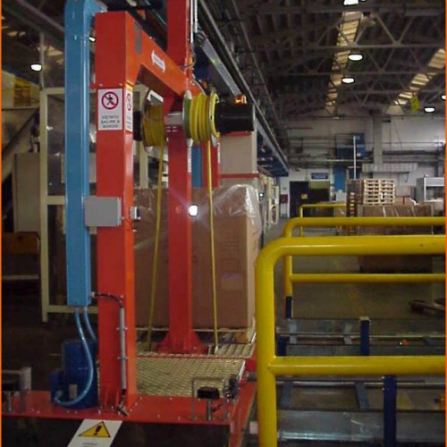
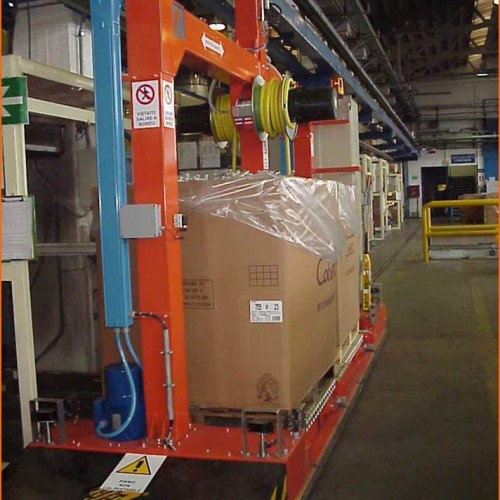
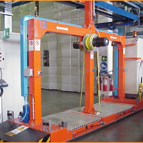
Plant for strapping, weighing and transport of aluminium billet
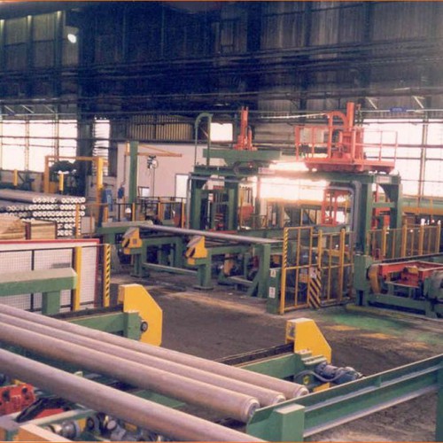
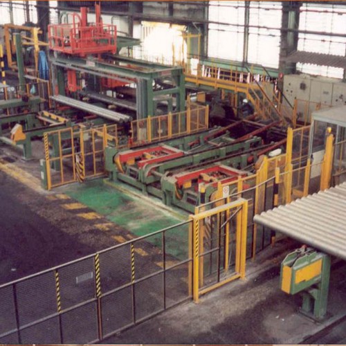
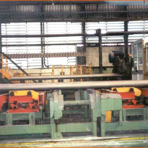
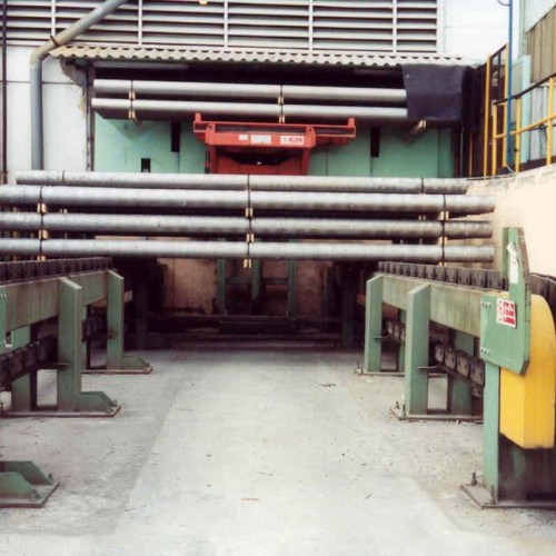
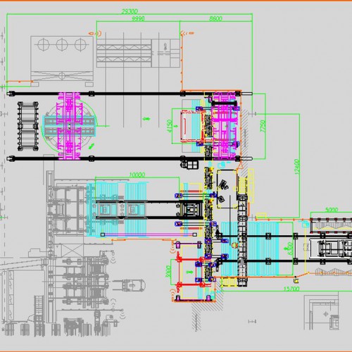
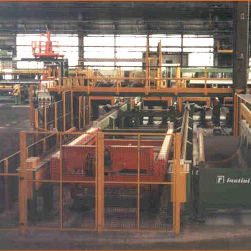
The plant in question, designed and built to perform the automatic weighing, strapping and transport of billets of aluminium, is in production at the Italian Alcoa plant at Portoscuso (CA). It is composed of a series of machines, positioned downstream of the existing plant for handling and cutting billets, that perform the operations of:
- alignment of billets, transport of billets to the location for forming package, forming package,
- transport package to the location for strapping and weighing, compacting billets, weighing pack,
- strapping pack with insertion of wooden heels, carrying strapped pack to position for marking, marking billets,
- transport package outside and stack, accumulation of stacks.
Dangerous areas of the plant are protected with protective mesh and light curtains.
-
Plant handling aluminium billets
For the company Alcoa Italy, plant at Portovesme (CA) there has been built a plant for handling aluminum billets.
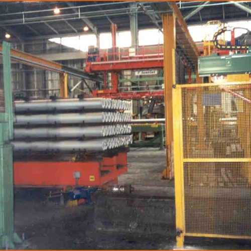
Starting from the extraction from the casting pit, the billets are first laid down on a conveyor, then conducted to a control station; from there, any damaged billets are diverted to an appropriate roller conveyor, while the suitable billets continue towards a layer forming station from which a manipulator picks up the number of billets established and deposits them on a turntable.Once the stack is formed, so that between the various layers of billets spacers are interposed, the platform rotates 90 ° to allow the Bernotti loader to withdraw the pile and transfer it to one of the homogenisation ovens.
At the end of homogenisation and cooling, the stack turns on the turntable so that after rotating 90 ° to allow unstacking, the manipulator picks up a layer of billets from the stack and one of the spacers, depositing the billets on a conveyor and the spacer into the appropriate storeroom. Advancing on the conveyor the billets come into position for a transfer device which picks up one billet at a time and deposits it on a special roller conveyor.
From this the billets arrive at the loading station of a shuttle that will load an appropriate number and transport them to the loading pallets of Sega Wagner. At the other end of the roller conveyor is the ELHAUS pallet and a transfer device; the pallet can act as a supply of the ELHAUS homogenisation furnace or send the billets from the ELHAUS plant to the shuttle or, finally, can receive billets discarded at the beginning of the cycle.
-
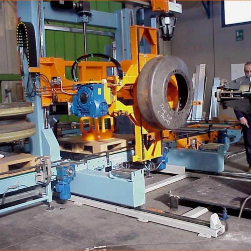
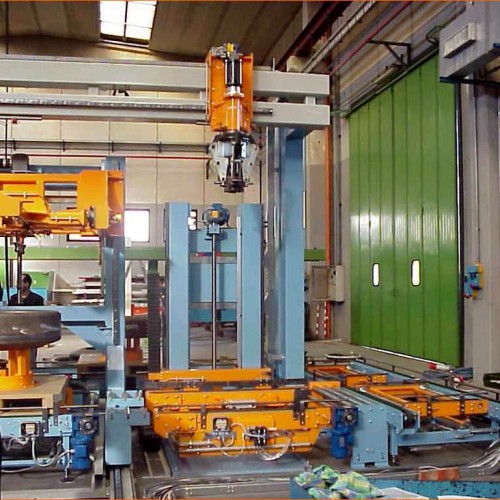
Plant for loading rubber rims
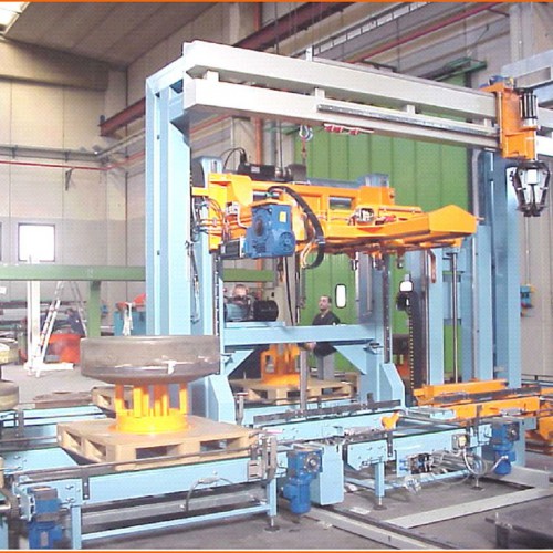
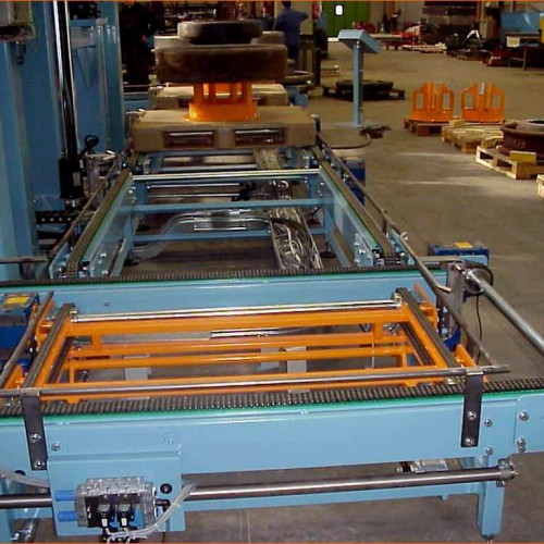
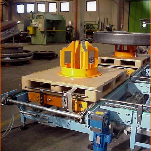
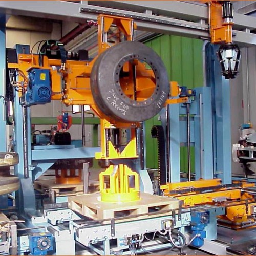
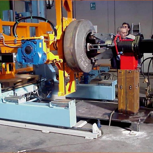
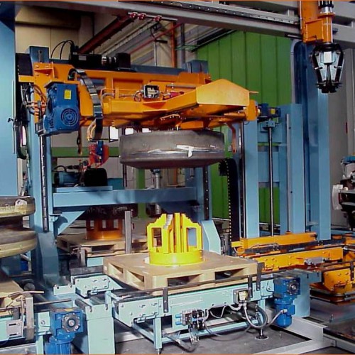
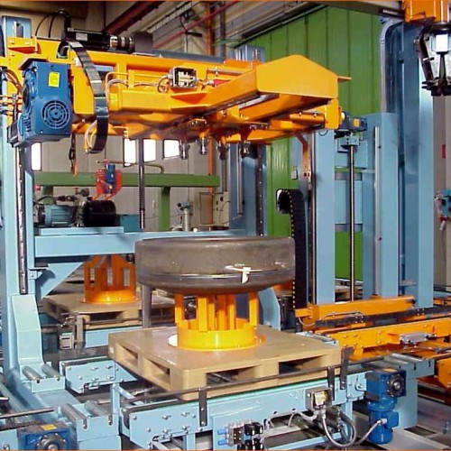
This machine or, more properly, set of machines, was realised for Caterpillar (USA), to be integrated in a complex installation. The plant was designed and built to perform automatic handling of rims to be “gummed” to a rotating carousel and the “gummed” rims from this to an output location.
The rims are moved on special pallets with special support devices. The plant is equipped with a zone for loading / unloading consisting of three chain conveyors; these bring the pallets with the worked rim and then, after the load is removed, the next rim to be gummed is loaded on them. At the end of loading the operator from the control panel executes the advancement of the pallet that proceeds to the conveyor upstream of the drawing unit of the loader; at this point the operator sets the control console of the machines used for the gumming the code for the type of rim to be worked: the code is transmitted to the PLC so that the machines will be ready for the format to be processed.
When the loader receives consent from the turntable (not supplied) to load the wheel rim, the pallet advances on the conveyor located underneath the gripping device, which after being positioned with the gripper oriented downward, drops to the predetermined height and then opens the arms of the gripper and finally raises the wheel rim and rotates it by 90 ° to present it frontally to the turntable.
Having performed the movements mentioned above, the loader advances, on rails fixed to the floor, towards the turntable and having passed the obstacle of the transporter underneath, moves vertically aligned with it; at the end of the translation, the loader sends a signal to the turntable that the rim is in position and, with coordinated movements of the gripping devices of the loader and of the turntable the passage of the rim to the turntable is achieved, and rotation of the turntable will take it to the gumming area.
When processing is performed the turntable presents the “gummed” rim in the same position from which it was taken and sends a signal to the loader consenting to removal. The loader is positioned appropriately and, with coordinated movements of the gripping devices it is transferred to the gripper of the loader which, when the operation is completed, reverses and rotates the gripper by + 90 ° or – 90 ° depending on the type of rim.
In fact, if no tilting is provided for, the rim will simply be released on to the pallet below, which, having received the load, will advance on the conveyors downstream until it reaches the unloading area; if, instead, loading is provided for then a special manipulator with a gripper will move into position, take hold of the rim and bring it into position for an elevator.
At the same time the empty pallet reaches the floor of the elevator, it will be brought to the correct height, and the gripper of the manipulator will release the rim onto it, and then the pallet with the rim on board will be carried to the height of the other transports on which the pallet will transit to reach the loading station.













 English
 Français
 Deutsch
 Italiano
 Español
 Português
 Türkçe